- yuanchenwujin@hotmail.com
- +86 335 3899 615
- 中文站
Product Details
Impact Test Frame
ANSI Z97.1 Impact Test Machine
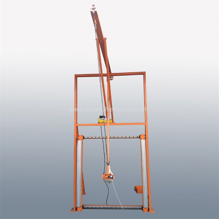
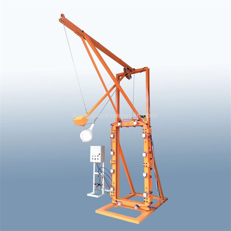
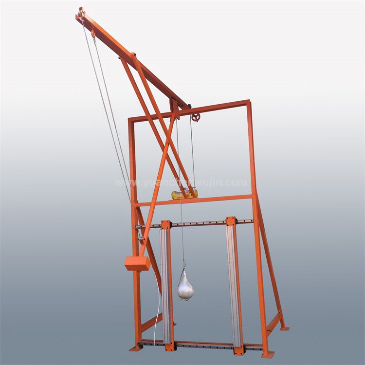
Impact Test Frame according to ANSI Z97.1. Including main frame, sub frame and 45 kg impactor. For samples 34 inches by 76 inches, ± 0.125 (1/8) inch (864 mm by 1930 mm, ± 3 mm)
Internal width: 33.25 inches ±0.2 inch (835 mm ±5 mm)
Internal height: 75.25 inches ± 0.2 inch (1902 mm ±5 mm)
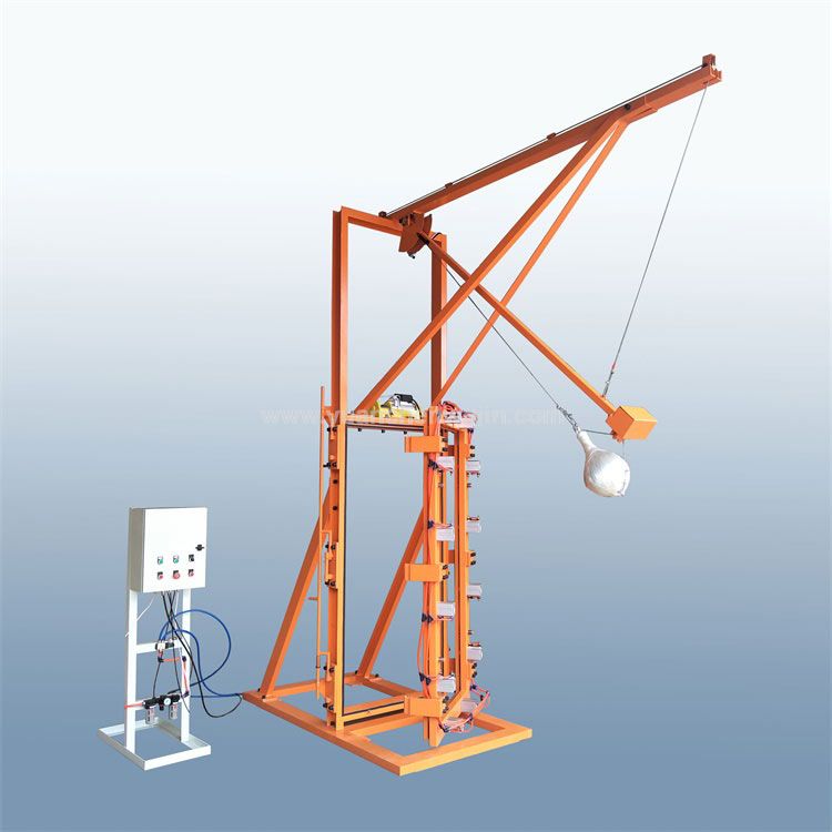
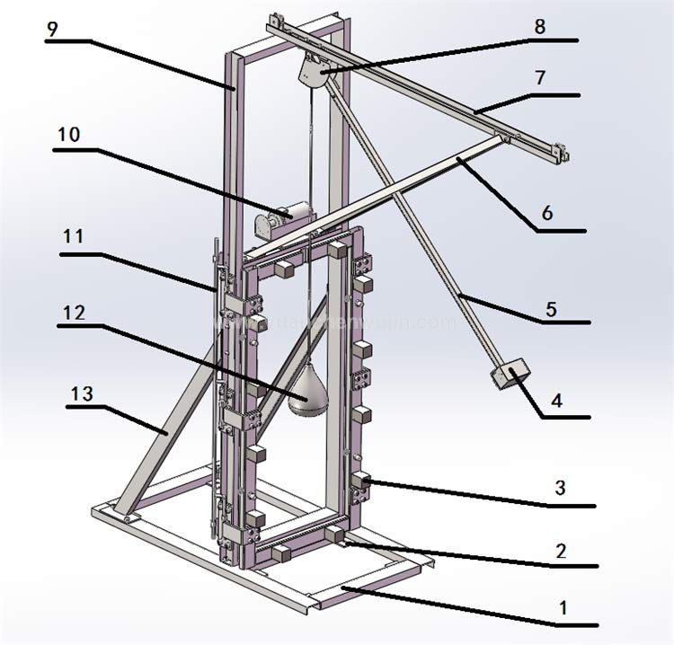
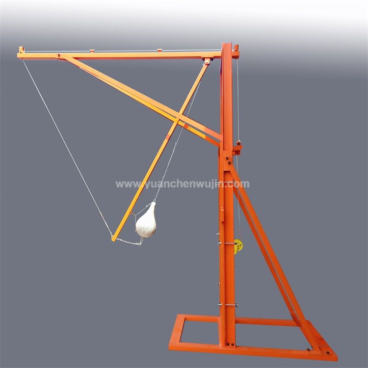
1: Bottom Frame 2: Anchor Bolt 3: Cylinder 4: Electromagnet Release Device
5: Swing Arm 6: Upper Inclined Support 7: Cantilever 8: Scale Dial 9: Main Frame
10: Electric Hoist 11: Control Rod 12: Shot Bag Impactor 13:Lower Inclined Support
Specification
The main frame shall be constructed to minimize movement, deflection, twisting or racking of its members during testing. For this purpose, the structural framing members shall be steel angles 3 inches by 5 inches by 0.25 inch (76 mm by 127 mm by 6 mm) or other sections and materials of equal or greater rigidity. The main frame shall be welded or securely bolted at the corners and braced
The main frame is mounted to a rigid floor and/or wall. Horizontal members made of steel sections connect the main frame to a rigid wall. The base beams are connected to the main frame by diagonal members of steel sections. Attach the two base beams of the main frame to a concrete base or floor using bolts M16 or equivalent.
Internal dimensions of main frame 3 (Figure 2) shall be:
Internal width: 33.25 inches ±0.2 inch (835 mm ±5 mm)
Internal height: 75.25 inches ± 0.2 inch (1902 mm ±5 mm)
The sub-frame for securing the specimens on all four edges consists of two parts made from wood or other material which is hard enough to withstand the pressure exerted by the clamping forces. Each part shall be provided with a groove or rebate in which a strip of
elastomeric rubber is laid; the specimen shall only contact the elastomeric rubber strips.
The inner sub-frame is in contact with the specimen, is 2- inches by 0.75 inch (50 mm by 19 mm) minimum. The outer part of the sub-frame holds the specimen and is 2 inches by 1.5 inches (50 mm by 38 mm) minimum.
The sub-frame is fixed to the main frame by at least twelve bolts (M10 bolts, scissors clamps or equivalent). These shall be fixed at the points with no fewer than two on any edge and spaced no more than 18 inches (450 mm) apart.
o provide and limit elastomeric rubber compression and avoid sub-frame distortion, non-compressible shims appropriate to glazing thickness shall be used to separate the inner and outer parts of the sub-frame. The elastomeric rubber strip, the only element of the sub frame that the test specimen shall come into contact with, shall be 0.8 inch (20 mm) wide by 0.4 inch (10 mm) thick and have a Shore-A hardness of 40 ± 10 (ASTM D2240, Standard Test Method for Rubber Property – Durometer Hardness).
NOTE: Modifications that clearly do not alter the function or performance of the main frame or sub-frame are acceptable. Any reasonable means may be used to secure the sub-frame to the main frame provided the mounting is secure and the pressure on the glazing specimen in the sub-frame is controlled.
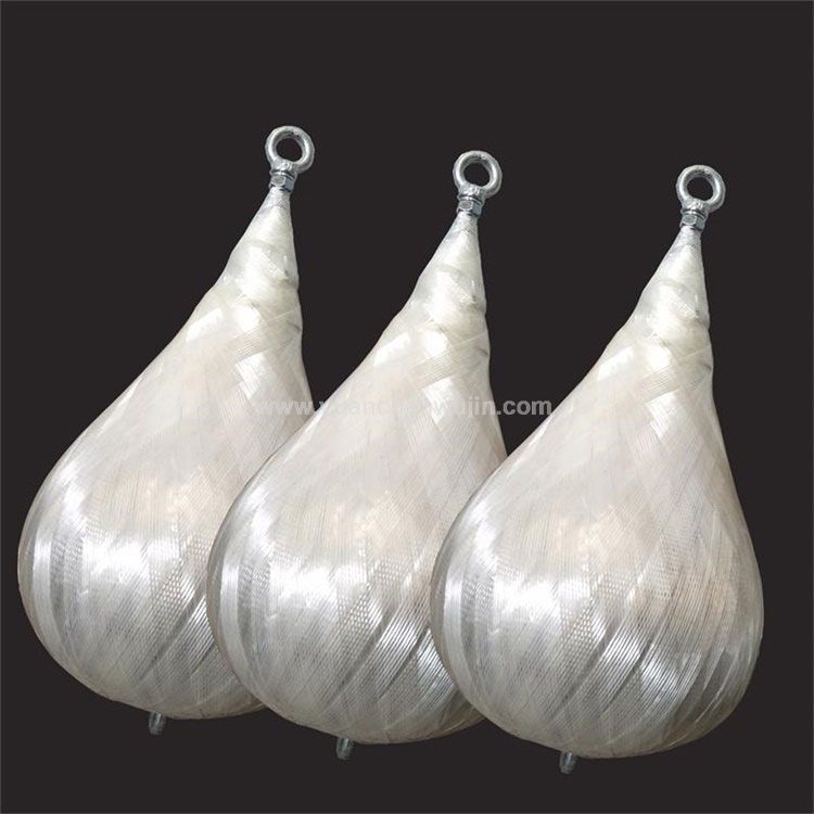
Shall consist of the leather bag, a commercial punching bag with its bladder left in place, or any other leather bag of nominally identical shape and size. The bag shall be filled with lead shot of 2.4 mm + 0.1 mm diameter (nominal USA No. 71/2 or European No. 7 lead shot) and taped. After filling with lead shot, the top shall be either pulled over the metal sleeve and tied with a cord; or twisted around the threaded eyebolt shaft and tied below the metal sleeve, or both. To reduce bag damage during testing, the exterior of the leather bag surface shall be completely covered with glass filament reinforced pressure sensitive polyester adhesive tape 5 , 0.5 inch to 0.6 inch (12 mm to 15 mm) in width and 0.006 inch (0.15 mm) thick.
Tape the entire bag, using three (3) rolls or 180 yards (165 m) total length, and taping in a diagonal-overlapping manner. Tape the neck of the bag separately, with additional glass filament reinforced tape of the same kind. The total mass of the impactor assembly shall be 100 lb. ±4 oz. (45.4 kg ± 0.2 kg), excluding traction system attachments.
To reduce bag deformation during testing, the bag shall be rotated about the axis of its suspension device before each specimen or sample set, by no less than 30 degrees, and by no more than 90 degrees. 4 Such as 9 inch (229 mm) diameter by 14 inch (356 mm) high Everlast 4207 (raw, full grain 3 ounce (85 grams)
The impactor is suspended by means of a single, stranded steel cable, approximately 0.125 inch (3 mm) diameter, from an upper swivel-fixture above the head of the main frame at an elevation of which the minimum distance between the swivel-fixture and impactor centerline is 60 inches (1524 mm).
The upper swivel-fixture must be rigid to ensure the point of suspension remains stationary. The lower swivel(s) or equivalent shall be provided on the bag for rotation of the impactor about its suspension device axes between impact events.
When at rest, the surface of the impactor, at its maximum diameter, shall be located no more than 2 inches (51 mm) from the surface of the specimen and no more than 2 inches (51 mm) from the center of the specimen.
Shall be used which enables the impactor to be brought into its launch position. The launch position depends on the drop height selected. The traction cable is connected to the impactor traction system by a
release mechanism, with provisions for rotating the impactor.
To position the impactor at the selected drop height, a traction force shall be applied to raise the impactor such that the axis of the impactor shall be aligned with the suspension cable, with the cable remaining taut. To ensure this, the top and bottom ends of the impactor shall be connected to the release device by a suitable link.
(1) Place and center each specimen in the sub-frame so each edge is encased in the elastomeric rubber strip to a depth of at least 0.4 inch (10 mm). With the specimen mounted, the elastomeric rubber strip shall not be compressed by more than 15% of its thickness. For bolts, torque shall be 15 ft-lb. + 4 ft-lb (20Nm+ 5Nm).
(2) Select a drop height classification. Rotate the impactor as required. Raise the impactor to the selected drop height intended for
classification and stabilize it. At the selected drop height, the suspension device shall be taut and the axes of the impactor and cable shall be in line.
(3) The impactor, stabilized in the launch position in a vertical plane normal to the test specimen, is released and falls without initial velocity or axial rotation. At least one impact shall occur on each test specimen. Unbroken specimens may be reused for higher classification impact testing.
